
Mobile Roller Screen (Multi-Stage Mud Stone Separator)
Processing Capacity: 80-550 t/h | Core Shaft Deck: 10-20 Multi-Stage Linkage Rollers | Industrial Sizing: Sticky Clay and Rock Segregation, Coal Gangue Separation, Landfill and Construction Demolition Rubbish Recycling.
The mobile roller screen (frequently designated as a multi-stage mud-stone separator) represents an advanced high-efficiency classification technology engineered specifically for severe material separation. It handles complex mixtures including high-moisture cohesive soil, heavy clay interlayers, mixed stone matrices, sand-gravel fractions, coal-gangue minerals, and varied solid municipal wastes (including fresh, stale, incinerated, or landfill debris).
Traditional grading plant layouts—such as heavy log washers, sand washers, rotary trommels, or high-frequency circular vibrating screens—rely on massive volumes of fluid water to clear sticky clays. This creates heavy burdens in arid zones or sites striving to hit modern zero-emission eco baselines. Hengtai's proprietary multi-stage roller linkage separator eliminates water-flushing circuits. It breaks and screens sticky materials through purely mechanical interaction directly on site, significantly reducing investment expenses and operational cycles.
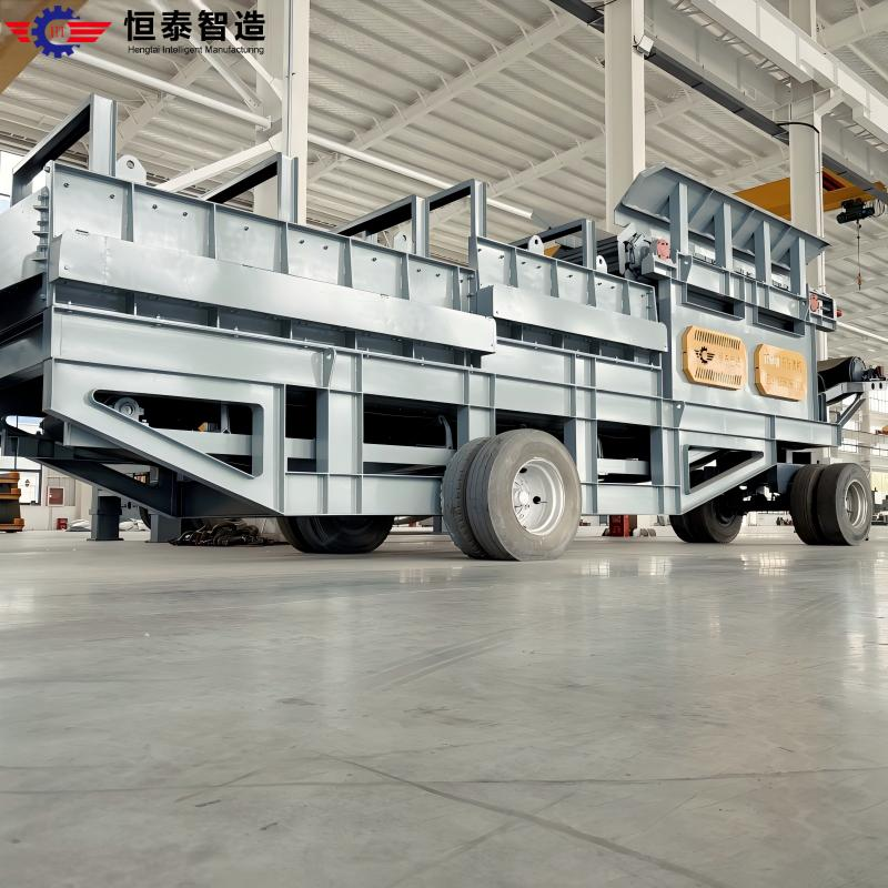
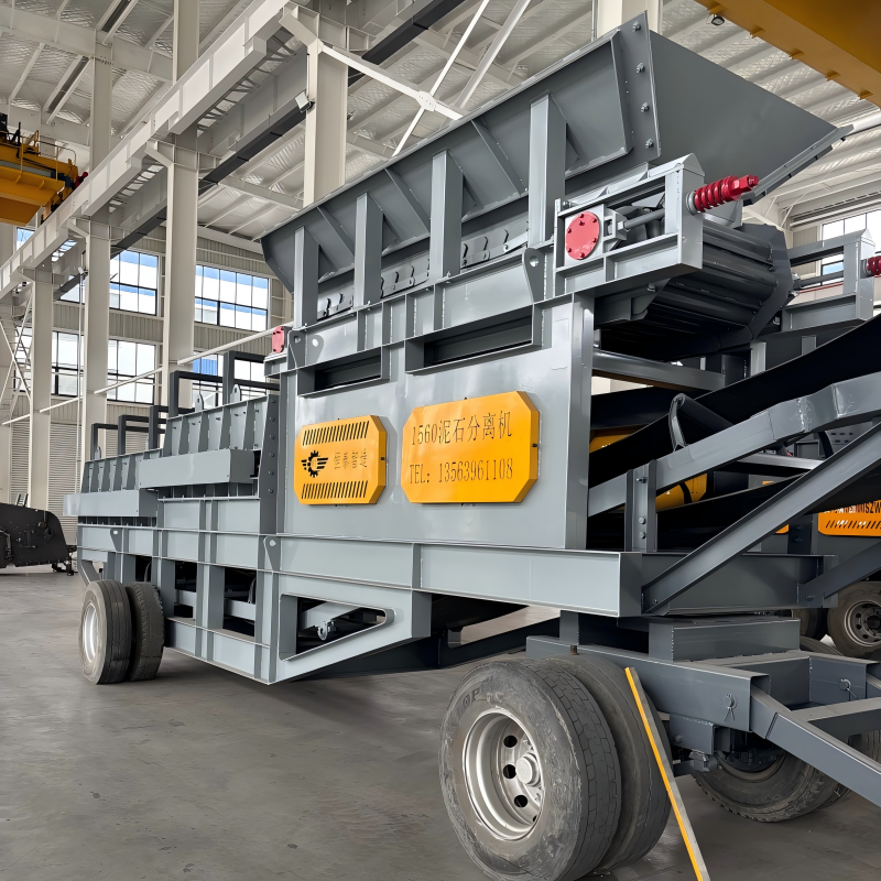
Product Layout & Field Application Showcase
Real factory layout designs and operational configurations for the multi-stage mobile roller separator line:
Onsite Processing Demonstration Video
Dual-Function Engineering Architecture
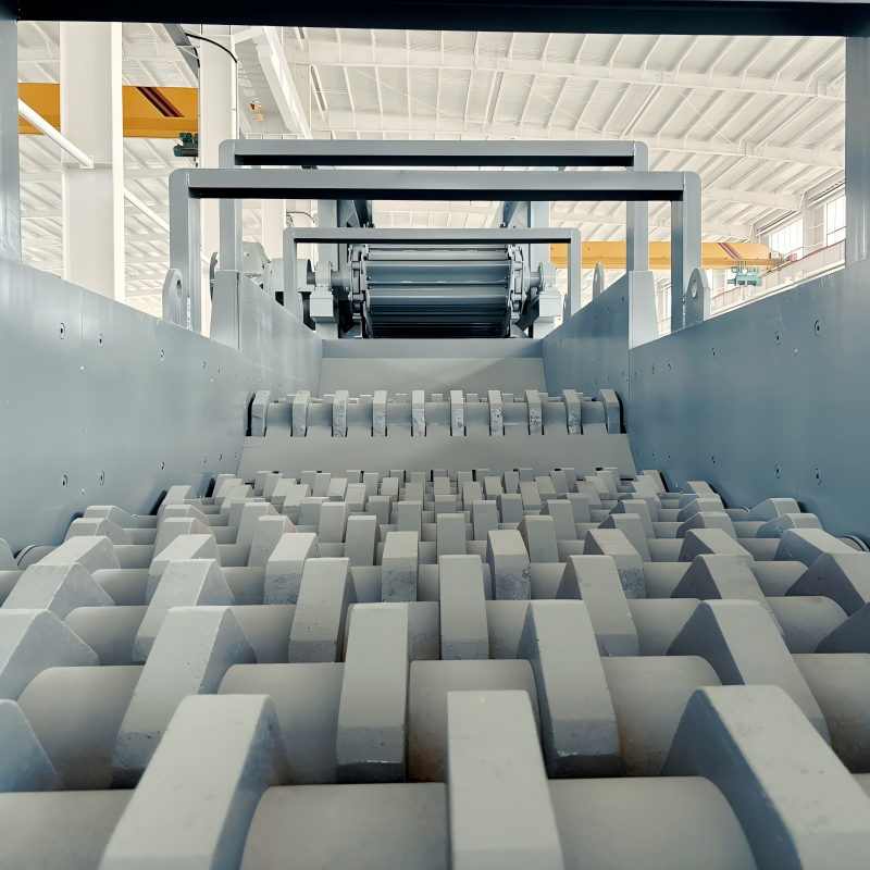
The plant features an innovative operational design that eliminates traditional screen binding while providing dual workflow capabilities:
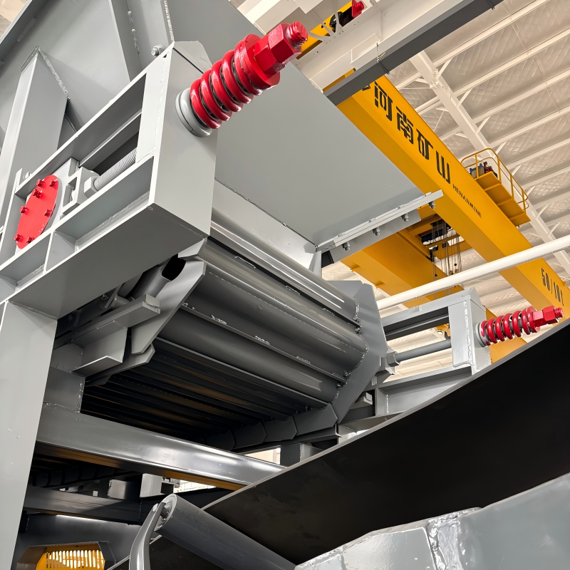
Simultaneous Feeding & Screening: The multi-shaft disc roller arrangement is often referred to as a "feeding screen." The forward-rotating eccentric rollers continuously advance large rocks while passing fine soils downward. This double action replaces independent primary grizzly feeders, optimizing system layout and lowering footprint costs.
Complete Mobile Plant Integration: Built onto a heavy-duty wheeled or crawler chassis, the station seamlessly integrates a primary hopper unit, a choice of a heavy-duty vibrating or chain apron feeder, the core roller separation screen assembly, independent cross-belt discharge conveyors, and a centralized electric control panel.
Commissioning & Operation Guide
Rotational Alignment & Dry Run Check: After leveling the chassis, close the main electrical circuits and verify that adjacent linkage motors rotate synchronously in opposite directions. Conduct a 10 to 20-minute empty dry run. If any abnormal structural resonance or gear noise occurs, halt the drive line immediately for diagnostic tracking.
Gradual Feed Loading: Once the rollers operate smoothly, introduce small volumes of material through the hopper. Confirm that larger fractions travel forward toward the discharge gate. Gradually scale up feed volumes until reaching the target operational throughput.
Fastener Inspection & Lubrication: Brand-new machinery requires immediate inspection of high-strength anchor bolts. Verify proper lubrication levels across all multi-shaft drive bearings and reduction gearboxes before full-load operation.
Variable Speed Optimization & Load Limits: Operators can adjust shaft rotation speeds using the Variable Frequency Drive (VFD) according to material moisture and specific gravity. Always ensure the roller deck is clear of material accumulation before starting or stopping the drive system.
Technical Specifications & Performance Parameters
Select the optimal mobile roller screen model based on your target width, shaft count, and volume demands:
| Model | Box Width (mm) | Effective Length (~mm) | Shaft Count | Motor Qty | Single Power (kW) | Matched Feeder | Capacity (t/h) | Mobility Type |
|---|---|---|---|---|---|---|---|---|
| XLY0810 | 800 | 2900 | 10 | 1 | 18.5 | LB7525 | 80 - 130 | Wheeled / Crawler |
| XLY1010 | 1000 | 2900 | 10 | 2 | 15 | LB8030 | 120 - 180 | Wheeled / Crawler |
| XLY1012 | 1000 | 3300 | 12 | 2 | 15 | LB8030 | 130 - 200 | Wheeled / Crawler |
| XLY1310 | 1300 | 3000 | 10 | 2 | 18.5 | LB1030 | 150 - 300 | Wheeled / Crawler |
| XLY1312 | 1300 | 3600 | 12 | 2 | 18.5 | LB1030 | 180 - 350 | Wheeled / Crawler |
| XLY1315 | 1300 | 4500 | 15 | 3 | 15 | LB1030 | 200 - 400 | Wheeled / Crawler |
| XLY1515 | 1500 | 4600 | 15 | 3 | 15 | LB1230 | 350 - 500 | Wheeled / Crawler |
| XLY1520 | 1500 | 6000 | 20 | 4 | 18.5 | LB1235 | 380 - 550 | Wheeled / Crawler |
* Note: Throughput rates vary based on material characteristics, mud moisture content, feed size distribution, and shaft gap configuration. Technical parameters are subject to continuous engineering updates without prior notice.
Industrial Diagnostic & Troubleshooting Matrix
Potential Causes: Insufficient screen box structural rigidity causing vibration harmonics; misaligned, non-level frame positioning; or erratic, overloaded surge feeding.
Engineering Remediation: Check and retighten structural side-plate bolts and crossbeams to ensure joint rigidity. Adjust chassis outriggers or support springs to restore a level operating surface. Regulate feed flow rates to ensure material spreads evenly across the rollers.
Potential Causes: Electrical short circuits or damaged control elements; electric motor breakdown; or excessive material accumulation overloading the drive line before startup.
Engineering Remediation: Inspect electrical lines, check terminal block insulation, and replace worn contacts. Check motor winding resistance and replace damaged drives. Clear heavy residual material from the roller deck before restarting.
Potential Causes: Operating the machine near its critical resonance frequency for extended periods, causing material fatigue; loose high-strength bolts; or severely deformed suspension springs causing uneven loading.
Engineering Remediation: Calibrate drive frequencies using the VFD to avoid critical resonance speeds. Implement a regular maintenance schedule to inspect and retighten high-strength side-plate fasteners. Replace deformed suspension springs immediately to ensure balanced load distribution.
Potential Causes: Low grease levels or contaminated, degraded lubricants; internal bearing wear; or over-lubrication blocking the labyrinth seal channels and causing heat buildup.
Engineering Remediation: Flush out degraded lubricants and replenish with high-grade bearing grease. Replace worn or damaged roller bearings. Maintain proper grease fill limits to ensure clear thermal venting pathways.
Potential Causes: Surge feeding creating a material layer that is too thick; operational blockages in the roller gaps; or loose, slipping drive belts reducing power transfer.
Engineering Remediation: Adjust feeder settings to maintain a thin, uniform material bed. Regularize deck cleaning schedules to remove stubborn debris from the roller gaps. Adjust or replace slipping drive belts to restore proper shaft torque.
Primary Feeding Solutions & Complementary Equipment
To optimize mud and rock segregation right from the first processing stage, the separator integrates seamlessly with our heavy-duty feeding systems:
Get Professional Technical Catalog & Factory Price Quote
Our engineering team develops customized mine setups based on your exact target capacity, geology profile, and regional power setups.